
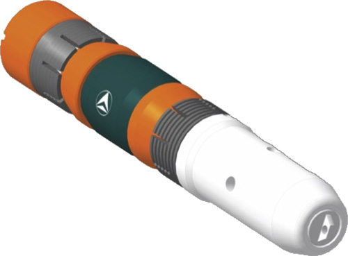
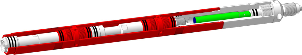
Explosive slip bridge plugs manufactured by LLC "Promperforator" consist of the plugging element (plug) and single-use or reusable setting tool.
Plugging elements are manufactured in various options:
- PVSh-PP.400 – plugs are used for disconnection of productive formations. They are made of aluminum alloy with iron slips (see Table 1).
- TIREX-PP – plugs are composite plugs used for installation of easy-to-drill isolation plugs (see Table 2). The plugs are сomponents of FRACline® assembly set in Plug-and-Perf technology.
- PVSh-PP-C.400 – are cementing packers. The special version is used to inject cement slurry to under-packer and annular space during well maintenance. The packers are installed above the non-pressurized interval (see Table 3).
- VrP – plugs are temporary plugs. It is a reliable and cost-effective solution for installation of an easy-to-drill isolation bridge in wells where resistance to pressure drops more than 40 MPa is not required. This plug type is more efficient replacement for VP-type aluminum packers (see Table 4).
- SKAT - plugs are packers with integrated expendable setting tools that do not require additional assembly and maintenance of reusable parts due to their absence. Plugging elements are made of aluminum alloy with cast iron anchors (see Table 5)
Plugging elements PVSh-PP.400, TIREX-PP, PVSh-PP-C.400 and VrP are installed with the help of setting tools PVSh-PP.300 (see Table 6) in a set with propellant charges ZPVSh-102PP (or slow-burning propellant charges ZPVSh-102PP (MG) or hydraulic setting tools IGP (see Table 7) or setting tools IPD-PP (see Table 8).
SKAT plugs are installed hydraulically by dropping the ball and pumping pressure into the tubing string and the disconnection of the plugging element can be carried out hydraulically or mechanically (tensile force or rotation) depending on the option.
Specific Features
- Lowering and installation of the plug is possible in vertical, directional and horizontal wells on TCP, wireline and coil-tubing.
- The plug has three levels of protection against premature installation while running in hole.
- A special adapter for each plug type is supplied together with composite plugs.
- The setting tool is adapted for work with other composite and soluble plugs made in Russia and abroad.
- Operational life of the setting tool is increased.
- It is possible to supply single-use explosive-type setting tools to eliminate errors during their assembly.
- A pattern for each plug type is supplied under a separate purchase-order.
- For installation of plugging elements on TCP with the help of hydraulic setting tools IGP it is sufficient to use the unit for pushing the initiating ball and pressure supply to the tubing (coil-tubing).
- It is possible to install the plugging element on wireline by non-explosive method using a two-stage setting AC power tools IPD-PP.
Table 1. PVSh-PP.400 Plug Technical Characteristics
| Parameter | Value | Product Appearance | |||||||||
|---|---|---|---|---|---|---|---|---|---|---|---|
| PVSh- 82PP.400 | PVSh- 88PP.400 | PVSh- 92PP.400 | PVSh- 97PP.400 | PVSh- 102PP.400 | PVSh- 110PP.400 | PVSh- 118PP.400 | PVSh- 135PP.400 | PVSh- 138PP.400 | PVSh- 146PP.400 | ||
| Outside diameter, mm | 82 | 88 | 92 | 97,8 | 102 | 110,5 | 118,8 | 136 | 138 | 146,8 |

|
| Setting tool name |
PVSh-82PP.300 in all design options, IGP-76-0,72, IPD-82PP |
PVSh-102PP.300 in all design options, IGP-98-1,28, IPD-102PP |
|||||||||
| Casing internal diameter, mm: | |||||||||||
| minimum | 88 | 94 | 98 | 104 | 109 | 117 | 125 | 144 | 146 | 154 | |
| maximum | 98 | 104 | 106 | 109 | 118 | 124 | 133 | 152 | 155 | 164 | |
| Installation force, not more, kgs | 11500 |
13000 |
14500 |
17000 |
|||||||
| Max allowable operating temperature, °С | 100* | ||||||||||
| Max allowable pressure difference between separated intervals, MPa | 70 | 50 | |||||||||
| Plug length, mm | 380 | 565 | 456 | 459 | 466 | 470 | 468 | 443 | 530 | 565 | |
| Plug mass, kg | 6,8 | 9,7 | 10 | 7,5 | 11,3 | 11,9 | 19 | 23,5 | 27 | 35,3 | |
|
* When working on wireline, it is permissible to use the plug in the wells with temperatures up to 150°С. |
|||||||||||
Table 2. TIREX-PP Plug Technical Characteristics
| Parameter | Value | Product Appearance | |||||||||||||||
|---|---|---|---|---|---|---|---|---|---|---|---|---|---|---|---|---|---|
| TIREX- 82PP | TIREX- 92PP | TIREX- 97PP | TIREX- 102PP | TIREX- 110PP |
TIREX- 114PP |
TIREX- 116PP |
TIREX- 118PP |
TIREX- 120PP |
TIREX- 135PP |
TIREX- 136PP |
TIREX- 138PP |
TIREX- 140PP |
TIREX- 146PP |
TIREX- 148PP |
TIREX- 150PP |
||
| Outside diameter, mm | 82 | 92 | 97 | 102 | 110 | 114 | 116 | 118 | 120 | 136 | 136 | 138 | 140 | 146 | 148 | 150 |

|
| Casing internal diameter, mm: | |||||||||||||||||
| minimum | 88 | 98 | 104 | 109 | 117 | 124 | 124 | 125 | 128 | 144 | 146 | 146 | 147 | 154 | 156 | 154 | |
| maximum | 98 | 104 | 109 | 118 | 124 | 130 | 130 | 133 | 135 | 152 | 152 | 153 | 156 | 164 | 164 | 165 | |
| Installation force, not more, kgs | 11500 | 13000 | 13000 | 14500 | 17000 | ||||||||||||
| Adapter sub name |
A-KP(AS)-82 A-KP(IN)-82 |
A-KP(AS)-92 A-KP(IN)-92 |
A-KP(AS)-97 A-KP(IN)-97 |
A-KP(AS)-102 A-KP(IN)-102 |
A-KP(AS)-110 A-KP(IN)-110 |
A-KP(IN)-114 | A-KP(IN)-116 |
A-KP(AS)-118 A-KP(IN)-118 |
A-KP(IN)-120 |
A-KP(AS)-135 A-KP(IN)-135 |
A-KP(IN)-136 | A-KP(IN)-138 | A-KP(IN)-140 |
A-KP(AS)-146 A-KP(IN)-146 |
A-KP(IN)-148 | A-KP(IN)-150 | |
| Setting tool name |
PVSh-82PP.300 in all design options, IGP-76-0,72, IPD-82PP |
PVSh-102PP.300 in all design options, IGP-98-1,28, IPD-102PP |
|||||||||||||||
| Max allowable operating temperature, °С | 100 | ||||||||||||||||
| Max allowable pressure difference between separated intervals, MPa | 70 | ||||||||||||||||
| Max load on the installed plug, t | 5 | ||||||||||||||||
| Length, mm | 668 | 575 | 465 | 633 | 822 | 385 | 385 | 830/870* | 487 | 840 | 490 | 490 | 490 | 870 | 490 | 490 | |
| Mass, kg | 2,9 | 3,1 | 4,3 | 4,2 | 6,4 | 6,3 | 6,3 | 7,5/12* | 6,3 | 10 | 10,6 | 10,6 | 10,6 | 12 | 10,6 | 10,6 | |
|
* Depends on the design option |
|||||||||||||||||
Table 3. PVSh-PP-C.400 Plug Technical Characteristics
| Parameter | Value | Product Appearance | ||||||
|---|---|---|---|---|---|---|---|---|
| PVSh- 97PP-C.400 | PVSh- 102PP-C.400 | PVSh- 110PP-C.400 | PVSh- 118PP-C.400 | PVSh- 135PP-C.400 | PVSh- 138PP-C.400 | PVSh- 146PP-C.400 | ||
| Outside diameter, mm | 97 | 102 | 110 | 118 | 135 | 138 | 146 |
|
| Setting tool name |
PVSh-82PP.300 in all design options, IGP-76-0,72, IPD-82PP |
PVSh-102PP.300 in all design options, IGP-98-1,28, IPD-102PP |
||||||
| Casing internal diameter, mm: | ||||||||
| minimum | 104 | 109 | 117 | 125 | 144 | 146 | 154 | |
| maximum | 109 | 118 | 124 | 133 | 152 | 155 | 164 | |
| Nipple channel diameter for slurry injection, mm | 15 | 20 | ||||||
| Max allowable operating temperature, °С | 150 | |||||||
| Max allowable pressure difference between separated intervals, MPa | 70 | 50 | ||||||
| Allowable axial load, ts, not more | 20 | |||||||
| Max pressure for slurry injection, MPa | 50 | |||||||
| Length, mm | 716 | 710/718* | 817 | |||||
| Mass, kg | 11,5 | 13 | 20 | 30/23* | 29 | 29,6 | 31 | |
| Nipple thread type | Thread 60 | Thread 73 | ||||||
| * Depends on the design option. | ||||||||
Table 4. VrP Plug Technical Characteristics
| Parameter | Value | Product Appearance | |||||||
|---|---|---|---|---|---|---|---|---|---|
| VrP-82 | VrP-92 | VrP-102 | VrP-110 | VrP-118 | VrP-138 | VrP-148 | VrP-158 | ||
| Outside diameter, mm | 82 | 92 | 102 | 110 | 118 | 138 | 146 | 158 |

|
| Casing internal diameter, mm: | |||||||||
| minimum | 88 | 99 | 107 | 117 | 128 | 144 | 156 | 164 | |
| maximum | 95 | 105 | 115 | 124 | 135 | 154 | 163 | 179 | |
| Length, mm | 182 | 182 | 188 | 196 | 200 | 205 | 205 | 252 | |
| Mass, kg | 2,4 | 2,5 | 2,6 | 2,7 | 2,8 | 3,0 | 3,1 | 4,0 | |
| Max allowable temperature, °С | 100 | ||||||||
| Max pressure difference between separated intervals, above the plug, MPa | 40 | ||||||||
| Max pressure difference between separated intervals, under the plug, MPa | 10* | ||||||||
| Setting tool name |
PVSh-82PP.300 in all design options, IGP-76-0,72 IPD-82PP |
PVSh-102PP.300 in all design options, IGP-98-1,28, IPD-102PP |
|||||||
| * In case of work on separating the interval with high reservoir pressure, pouring a cement bridge is required. | |||||||||
Table 5. SKAT Plug with integrated expendable setting tools Technical Characteristics
| Parameter | Value | Product Appearance | ||||||||||||||
|---|---|---|---|---|---|---|---|---|---|---|---|---|---|---|---|---|
| SKAT 90 | SKAT 100 | SKAT 110 | SKAT 118 | SKAT 120 | SKAT 136 | SKAT 138 | SKAT 144 | SKAT 160 | SKAT 180 | SKAT 206 | SKAT 240 | SKAT 265 | SKAT 302 | SKAT 306 | ||
| Outside diameter, mm | 91,1 | 99,8 | 109,4 | 118 | 119,3 | 136,3 | 138 | 144,2 | 160,2 | 180,8 | 206,2 | 239,5 | 265,0 | 301,7 | 358,6 |

|
| Casing internal diameter, mm: | ||||||||||||||||
| minimum | 97,2 | 105,5 | 118,6 | 126 | 124,2 | 142,1 | 144 | 150,8 | 168,3 | 186,7 | 214,1 | 245,3 | 273,6 | 309,2 | 370,2 | |
| maximum | 103,9 | 115,8 | 128,1 | 132 | 134,3 | 155,8 | 152 | 161,7 | 180,9 | 205,7 | 230,2 | 258,9 | 283,2 | 322,9 | 387,3 | |
| Installation force, not more, ton | 15 | 15 | 15 | 15 | 15 | 22,7 | 15 | 22,7 | ||||||||
| Installation pressure, not more, MPa | 24 | |||||||||||||||
| Max allowable temperature, °С |
138 |
120 | 138 | 138 | 120 | 138 | ||||||||||
| Max allowable pressure difference between separated intervals, MPa | 70 |
50 |
35 | 27,5 | 21 | 10,5 | ||||||||||
| Connecting thread | By agreement with the customer | Tubing73 | By agreement with the customer | Tubing73 | By agreement with the customer | |||||||||||
| Length, mm | 417 | 421 | 711 | 835 | 435 | 480 | 900 | 480 | 485 | 498 | 558 | 615 | 575 | 693 | 705 | |
| Mass, kg | 16,6 | 20,8 | 23,0 | 40,3 | 25,2 | 32,0 | 58,0 | 35,0 | 39,0 | 49,0 | 58,5 | 60,7 | 60,0 | 84,5 | 118,0 | |
Table 6. PVSh-PP.300 Setting Tool Technical Characteristics
| Setting tool name | Parameter |
Product Appearance |
|||||||
|---|---|---|---|---|---|---|---|---|---|
| Outside diameter, mm | Max force generated, ts | Min casing drift diameter, mm1) | Max allowable hydrostatic pressure, MPa | Length, mm | Mass, kg | Max allowable temperature, °С | Operational life, settings | ||
| PVSh-82PP.300 | 82 | 17 | 88 | 100 | 832 | 24,6 | 150 | 1/52) |

|
| PVSh-82PP.300 FL | 780 | 23,4 | |||||||
| PVSh-82PP.300 FL-3 | 838 | 26,0 | |||||||
| PVSh-82PP.300 FL-4 | 780 | 120 | 5 | ||||||
| PVSh-82PP.300 FL-4 140 MPa | 140 | ||||||||
| PVSh-102PP.300 | 102 | 27 | 109 | 100 | 855 | 38,8 | 150 | 1/52) | |
| PVSh-102PP.300 FL | 805 | 37,4 | |||||||
| PVSh-102PP.300 FL-3 | 863 | 45,0 | |||||||
| PVSh-102PP.300 FL-4 | 805 | 43,4 | 120 | 5 | |||||
| PVSh-102PP.300 FL-4 140 MPa | 140 | ||||||||
| PVSh-82PP.300DS | 82 | 25 | 88 | 100 | 1180 | 32,8 | 150 | 10 | |
| PVSh-82PP.300DS (FL) | 31,6 | ||||||||
| PVSh-102PP.300DS | 102 | 40 | 109 | 1260 | 62,0 | ||||
| PVSh-102PP.300DS (FL) | 60,6 | ||||||||
|
1) Depends on the plug type. 2) Depends on the delivery set (one salvo or five salvos). |
|||||||||
Table 7. IGP Hydraulic Setting Tool Technical Characteristics
| Parameter | Value | Product Appearance | |||
|---|---|---|---|---|---|
| IGP-76-0,72 | IGP-98-1,28 | ||||
| Outside diameter, mm | 76 | 98 |

|
||
| Top connecting thread | Tubing60 | Tubing73 | |||
| Max external pressure, MPa | 96 | ||||
| Max internal pressure (liquid column + applied pressure), MPa | 120 | 100 | |||
| Max allowable operating temperature, °С | 170 | ||||
| Traction capacity at pressure 1 MPa, t |
0,72 |
1,28 |
|||
| Working stroke distance, mm, not less | 140 | 200 | |||
| Max inclination angle of the well | Not limited | ||||
| Load capacity, t, not more | 40 | 46 | |||
| Length, mm |
1692/1710* |
1527/1617* |
|||
| Mass, kg |
37/42* |
40/48,5* |
|||
| * Depends on the design option. | |||||
Table 8. IPD-PP Two-Stage Setting Tool Technical Characteristics
| Parameter | Value | |
|---|---|---|
| IPD-82PP | IPD-102PP | |
| Outside diameter, mm | 82 | 102 |
| Casing min drift diameter, mm* | 88 | 109 |
| Max external pressure, MPa | 150 | |
| Max allowable operating temperature during 1 hour, °С | 150 | |
| Max traction force created by IPD, ts | 25 | 40 |
| Length, mm | 1180 | 1260 |
| Mass, kg | 30 | 62 |
| Operational life, settings, not less | 20 | |
| Type of thermo-gas generator | TTG PSh | |
| * Depends on the plug used. | ||
|
||